AeroSports
Game Controllers & Sensor Network
Realtime controller and sensor network powering gameplay interactions across rooms, from USR RS422-over-Ethernet systems to custom Arduino and ESP-based controller stacks.
Backbone
USR-N510 / USR-N540
Network
RS422 to Ethernet controller chain
Controllers
Custom Arduino + ESP
Telemetry
Realtime sensor state updates
Engineering
Protocol + hardware layout design
Tech Stack Overview
Grouped by the primary systems, languages, and infrastructure used in this build.
Frameworks
Arduino
Languages
C++
Infrastructure
HTTP Socket, COM Socket, Ethernet
Hardware
ESP chips, USR-N510, USR-N540, Game sensors, Targets
AeroSports
Game Controllers & Sensor Network
Realtime controller and sensor network powering gameplay interactions across rooms, from USR RS422-over-Ethernet systems to custom Arduino and ESP-based controller stacks.
Backbone
USR-N510 / USR-N540
Network
RS422 to Ethernet controller chain
Controllers
Custom Arduino + ESP
Telemetry
Realtime sensor state updates
Engineering
Protocol + hardware layout design
Tech Stack Overview
Grouped by the systems, languages, and supporting layers used in this project.
- Frameworks
- Arduino
- Languages
- C++
- Infrastructure
- HTTP Socket, COM Socket, Ethernet
- Hardware
- ESP chips, USR-N510, USR-N540, Game sensors, Targets
Handles sensor input, controller traffic, and target-level room communication.
Overview
This project covers the gameplay-specific controller and sensor layer used across the facility.
Unlike the shared room infrastructure devices, these controllers and sensors are directly tied to gameplay interaction.
They include:
- USR-N510 and USR-N540 controller systems
- room-specific controllers such as Climb controllers
- custom Arduino Mega controllers for Laser
- ESP-based controller systems for Recipe
- multiple forms of light sensors / interactive targets
This layer is responsible for translating runtime commands from the game engine into physical room behavior and returning player interaction state back into the software runtime.
Architecture
Gameplay controllers sit between the game engine and the physical room devices, translating runtime commands into light and sensor behavior and returning interaction data back into the software runtime.
Controller Types
USR Controller Backbone
For most games, we use the following controller families:
-
USR-N510
-
1-port controller
-
used for games with fewer light sensors
-
examples: HexaQuest, Basket
-
USR-N540
-
4-port controller
-
used for larger sensor networks
-
examples: TileHunt, CTarget, PushButtons
These were configured using RS422 -> Ethernet protocol.
Although the controller itself has one IP address, each port can use its own dedicated socket ports for sending and receiving.
The controllers send light sensor state updates roughly 20 times per second in hex format.
Each port controls its own separate sensor sequence, which is important because:
- signal intensity stays more stable
- the data stays in a manageable size
- processing remains efficient
USR controllers also expose a built-in web interface that allows:
- checking signal quality
- changing IP addresses
- changing socket ports
- reviewing controller settings
Sensor / Target Types
The connected targets vary by room and gameplay style.
Examples include:
- floor tiles for TileHunt
- wall tiles that register ball hits in Hexa
- laser-sensor LEDs on the wall for CTarget
- push buttons and other room-specific target devices
The light sensors themselves include built-in RGB LEDs:
- controllers send color information to the targets
- sensors send active/inactive state back to the controller
Climb Controller Setup
Climb uses a separate controller system for its main wall interactions.
It includes:
- separate controller/receiver hardware
- 4 separate ports handling 4 different sequences
In addition, Climb also uses:
- floor tiles
- a USR-based floor tile controller layer
That means the room can involve:
- 3 controllers
- plus the PC
- all connected through a switch
Laser Controller Setup
Laser Escape uses a custom controller stack.
It includes:
- 4 Arduino Mega controllers
- each handles 48 devices
- total:
- 96 lasers
- 96 sensors
Split:
- 2 controllers for lasers
- 2 controllers for sensors
These communicate to the PC via COM ports.
Laser also includes:
- push buttons controlled by a USR controller
Recipe Controller Setup
Recipe does not use traditional light sensors.
Instead:
- each station has an NFC scanner
- a plate is scanned to interact with the station
The room is controlled through:
- a proxy/server ESP
- connected to the kiosk through COM
- and connected wirelessly to 7 client ESP chips
Device Flow
At a high level, the controller flow works like this:
- the Game Engine sends commands to the controllers
- controllers perform actions on the physical devices
- player interaction is detected by the devices
- controllers send that interaction state back to the engine
Communication style depends on the controller family:
Socket-based controllers
Used by:
- USR controller systems
- Climb controller systems
These communicate with the PC using socket communication over Ethernet.
COM-based controllers
Used by:
- Arduino-based systems
- many custom controller devices
These communicate through COM ports.
This made the controller layer flexible enough to support:
- standard reusable controller setups
- room-specific custom hardware where needed
Interface Evolution
Early stage
Initially, we were only using USR controllers. That gave us a stable foundation for:
Initially, we were only using USR controllers.
That gave us a stable foundation for:
- light sensor interaction
- color control
- basic room communication
Climb expansion
The next major step was Climb, which introduced: This hybrid setup expanded what kinds of room mechanics we could support.
Laser expansion
A major shift came with Laser Escape, where we built our own controllers and protocol. The hardware stack included: This was the first time we full...
Recipe expansion
Recipe introduced another new direction: Each expansion pushed the controller network beyond a single standard pattern and made the system more fle...
Challenges
1. Understanding USR controllers and socket communication
The first challenge was understanding the USR controller model and how to use socket communication effectively in practice. Although I already knew...
The first challenge was understanding the USR controller model and how to use socket communication effectively in practice.
Although I already knew the basics of networking and sockets, this project made it much more applied.
Important things to learn included:
- daisy-chain wiring
- per-port socket behavior
- controller protocols
- communication handler design
- deciding sequence layouts
- signal quality and power distribution
- choosing an optimized number of devices per sequence
All of these were new in this context, but connected naturally with the things I already knew.
2. Working with different sensor types and layouts
Another challenge was adapting different types of physical targets into a common controller model. Even though games looked very different physical...
3. Reverse engineering the Climb controller protocol
Climb was a major challenge because I was not given protocol documentation. I only had: So I used: to reverse engineer the protocol and build the c...
4. Choosing the right floor detection approach for Climb
Another challenge in Climb was deciding how to detect whether players had fallen off the ledge. The choice was between: We explored motion sensors...
5. Designing the Laser protocol and wiring topology
Laser was a major challenge. At first, we had controller ideas that split the system differently: That could work logically, but the physical wirin...
My Contribution
I worked on both the software protocol side and the physical hardware design side of this controller network.
My contribution included:
- learning and implementing USR controller communication
- building communication handlers
- designing controller layouts and sequence structures
- documenting room layouts for installation teams
- reverse engineering the Climb protocol
- designing and improving the custom controller protocol for Laser
- helping expand the system from standard preprogrammed controllers into fully custom controller stacks
This project involved a lot of research, experimentation, and iteration, but it became one of the most interesting parts of the facility because it connected physical gameplay directly to the software runtime.
Tech Used
Core technologies
 Arduino
 C++
C++Supporting technologies
Related Projects
Other projects from the same platform and codebase.
Kiosk Host & Room Control (.NET WebView)

WinForms orchestration layer between the Kiosk UI, Scorecard UI, Game Engine, backend API, and room hardware.

 WCPUS
WCPUS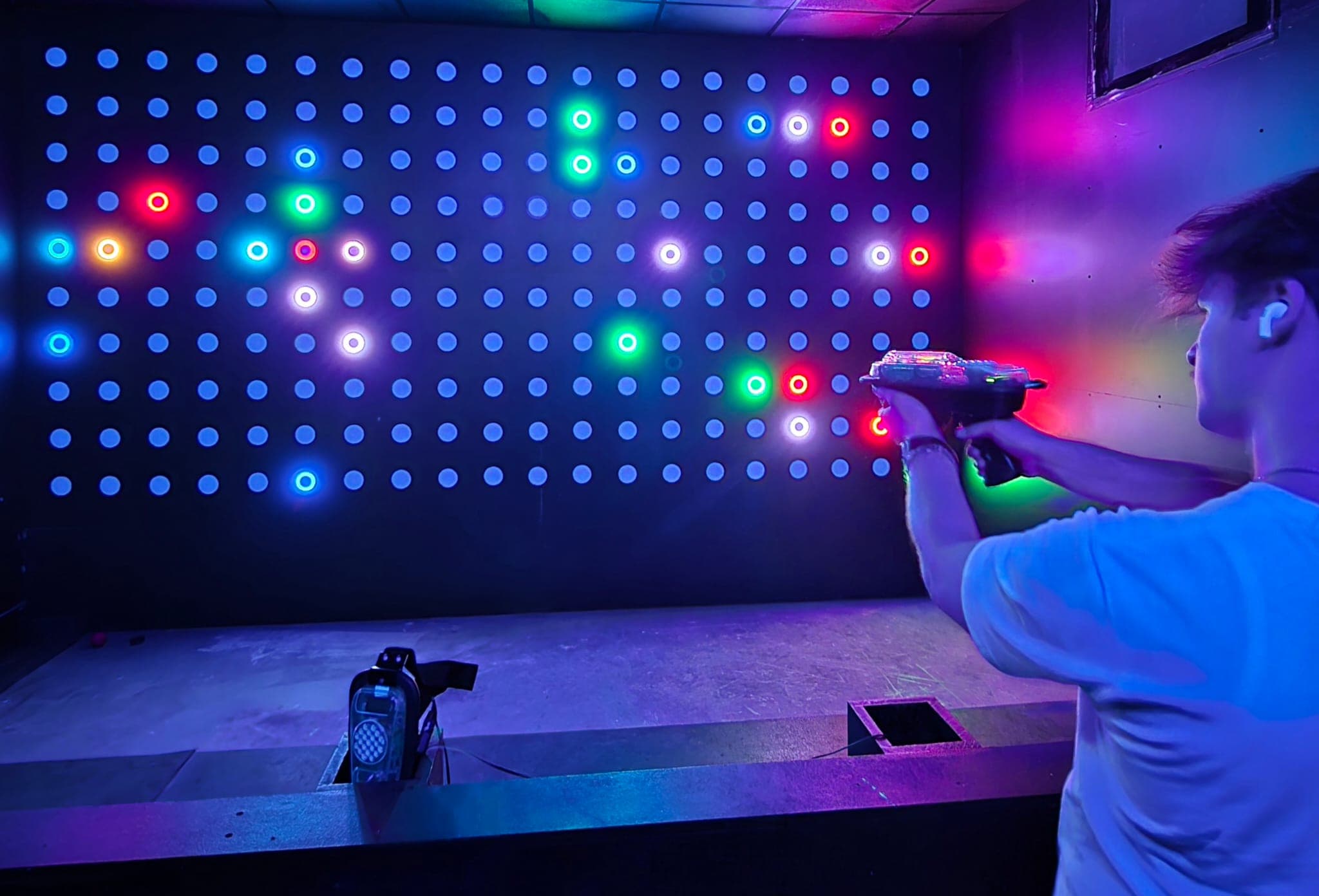
Game Engine (.NET Console Runtime)
Realtime .NET runtime that launches game variants, manages controller communication, executes game logic, and coordinates restart flow with the kiosk system.
SRE+1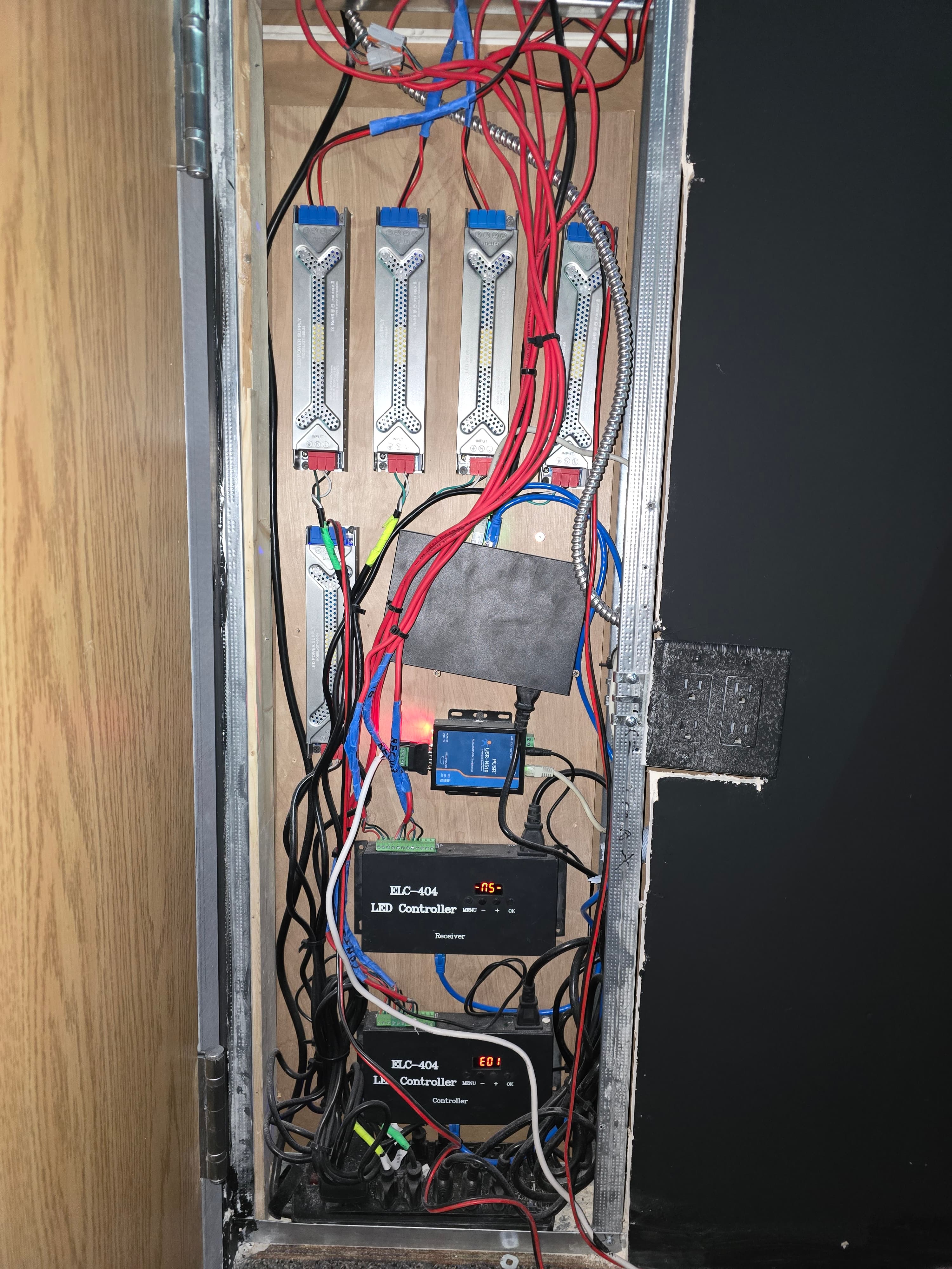
Room Devices & Common Room Infrastructure
Shared room-level device and communication infrastructure for displays, audio, wristband scanning, restart controls, door locks, and controller connectivity across interactive game rooms.
 CPE+2
CPE+2